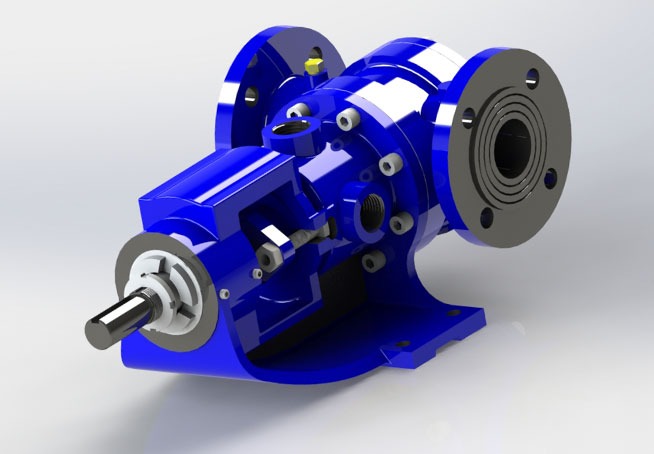
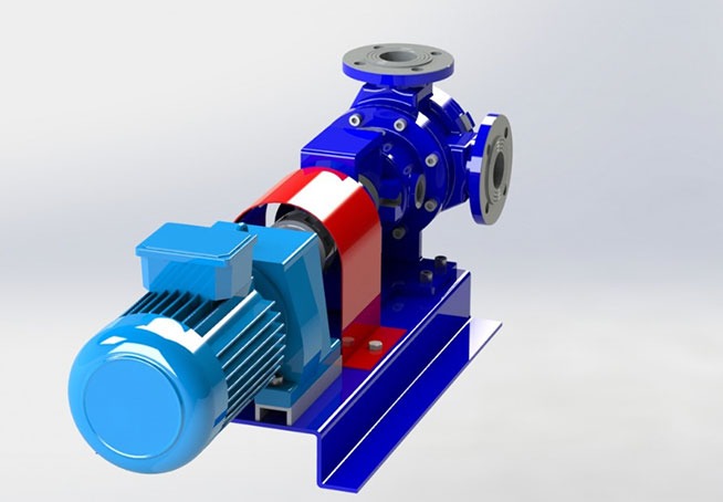
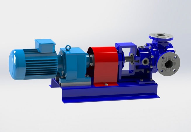
Internal eccentric gear pumps are positive displacement pumps with a wide range of applications. They are ideal for transferring high-viscosity fluids such as asphalt, tar, molasses, corn syrup, and chocolate. They are also frequently used for transferring low-viscosity fluids such as ammonia and fuel oil.
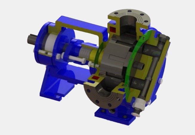
Internal eccentric gear pumps have two main moving parts: the ring gear and the idler gear. Therefore, they are reliable, have a long service life, and are easy to maintain.
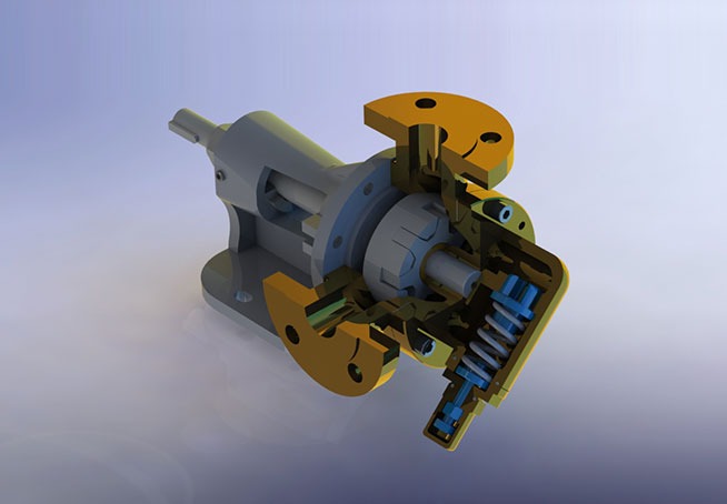
These pumps, capable of operating in both directions, have a wide viscosity range as well as a wide temperature range. Our manufactured internal eccentric gear pumps can be used in fluids up to 370ºC, and their outlet pressure is a maximum of 14 bar, depending on the fluid viscosity. During pump operation, the ring gear transmits the rotational movement it receives from the pump shaft to the idler gear.
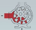
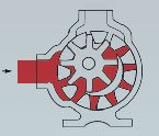
With each revolution of the pump, the gears separate at the suction port, creating a vacuum and forcing liquid into the pump. As the liquid flows between the gear gaps, the crescent-shaped seal on the pump cover separates the liquid and prevents it from flowing from the discharge port to the suction port.
When the gears interlock again at the discharge port, the volume decreases, and the resulting pressure pushes the liquid outwards.
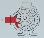
With each rotation of the pump shaft, an amount of liquid equal to the pump’s volume is transferred. Therefore, the pump’s capacity is directly proportional to its size and speed. The working principle of internally eccentric gear pumps is schematically shown below.
Advantages:
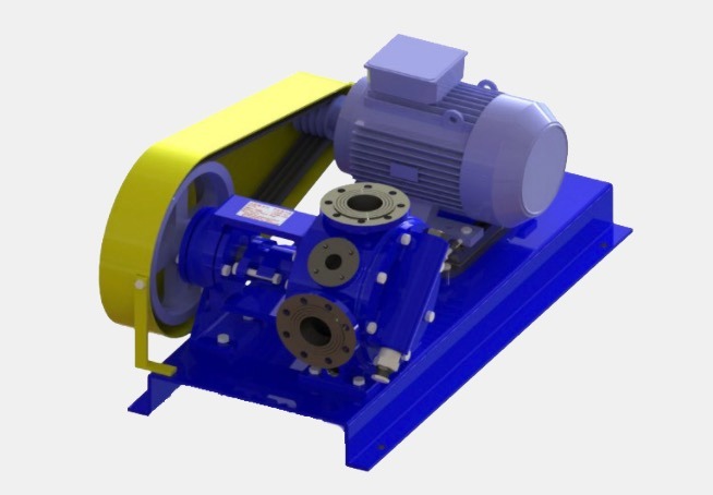
Extremely easy installation.
Wide range of shaft seals: packing, single mechanical seal, double mechanical seal and magnetic coupling.
Suitable for use in stainless steel, carbon steel, ductile iron and cast iron production.
Our gear units are suitable for various industries including:
Chemical;
Oil refining;
Paint and varnish, rubber and foam production;
Pharmaceutical;
Food processing, construction materials production, etc.